

Work Instructions
Work Instructions
15.6kWh Atlas ESS Battery
Cell Balancing
The cells that make up a battery are balanced together by placing them on a work table and connecting them in parallel with a power supply. The power supply is set to put out 200 amps at 3.5v for 2 hours.
After 2 hours the power supply is turned off and the cells are left connected for 6 hours.
After 6 hours the cells are disconnected and the voltage of each cell is measured. All cells should read the same voltage +-.1v. Place in quarantine all reject cells. The cells can now be used to assemble a battery module. For example, 16 cells are used to build a 48v battery (51.2v nom). These 16 cells are arranged in parallel, 2 rows of 8 cells to batter utilize work space.
Battery Box Riveting
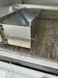
Rivet the bottom, sides and negative end plate together using 3/16x.5” al pop rivets and the pneumatic rivet tool. 2v nom). This forms an open trough with one end of the battery box open. This makes insertion of the cells easier.
Battery Box Assembly 1P8S
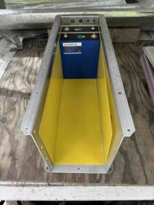
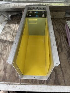
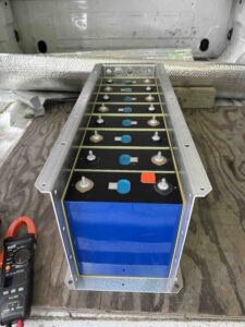
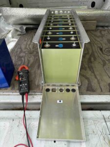
Insert the fibre glass insulating plates on the bottom and 2 sides of the box. Insert 8 cells into the box starting cell #1 with the negative terminal on the left side of the negative end plate (when viewed from the negative end). Cell #2 is inserted next with the positive terminal on the left. Insert cell separator plates between each cell and the box. There are 9 plates. The cells terminals alternate left, right as the cells are inserted into the box. This arrangement of cells is called 1P8S for one parallel, 8 series.
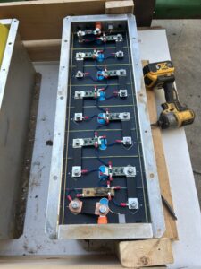
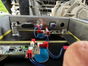
Place the bus bars onto the cell terminals making a series connection of plus to negative terminals. Copy the placement of bms cell boards, fasteners and jumpers onto the terminals as shown in the photo.
Place the standoff for mounting the fuse on cell #8. Ensure the M6 screw holding the fuse blade is clamping the fuse. See photo.
Place a Z bent and shaped bus bar onto the neg terminal on cell #1. See photo.
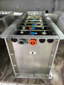
Install the orange bulkhead connectors onto the battery box end plates as shown in the photo.
Install the hole plugs and breather vent into one end plate as shown in the photo.
Install bus bars, bms cell boards and jumpers as shown in photos
Battery Module Testing
Measure the resistance of the cell loop. It should be approx 6 ohms for 8 cell boards in series.
Measure the voltage. It should read 3.31v x 8 = 26.48v
Power Distribution Module
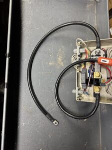
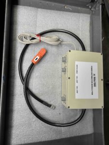
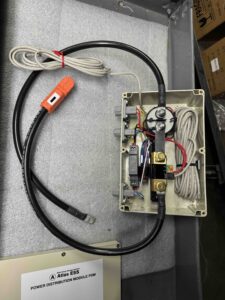
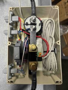
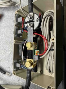
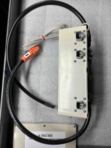
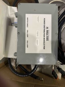
Wire the PDM internal components following the sample then insert the assembly into the plastic box. Install the Deutsche bulkhead connectors. Install the BMV-700 shunt and RJ11 cable. Install power cables.
Switch Cable
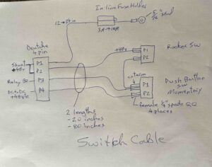
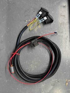
Fabricate the individual wires for the switch cable following the BOM and sample cables. Install the switches into a four switch bezel or a 5 switch bezel. Connect the 1/4” quick connects to the switches as per the sample. Connect the in-line fuse holder with fuse. Install the 3/8” split loom over the wires as per the sample.
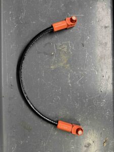
Power Cables 3
There are 3 different power cables. Fabricate following the samples
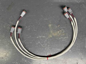
Cell Loop Cables 3
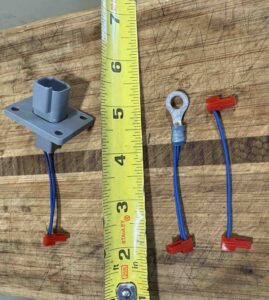
There are 3 cell loop cables. Fabricate following BOM and samples.
AC Heater Kit & DC Heater Kit
Fabricate heater kits and insulation following BOM and samples
System Testing.
Assemble battery system on bench and connect shop QuiQ battery charger. Turn on battery. Connect charger to 120vac. Observe that charger charges battery. BMV-700 works properly. Allow to charge for 15 min or until satisfied all is working.
Shipping
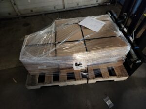
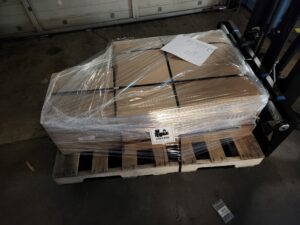
Battery is packed inside custom 2 piece box with foam padding reclaimed from LFP Cell shipping boxes. Batteries are shipped on standard wooden pallets 48”x42” or similar. Boxes strapped to pallet with steel strapping and shrink wrapped. See photo.
Photos of battery assembly
OVERVIEW
It takes several hours to install an Atlas ESS battery into a Ranger EV. These photos show the process in great detail. It is not difficult.
Click on the links below for more information
Installation Instructions Ranger EV R2
https://atlas-ess.com/support/
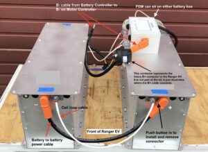
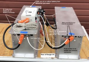
The battery boxes will sit inside your Ranger as shown in these photos
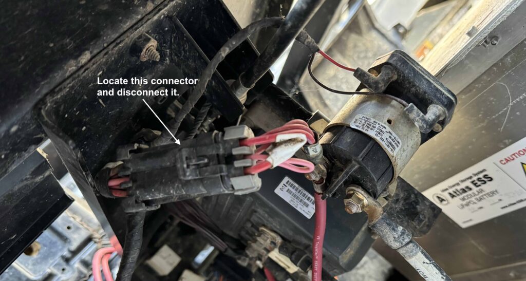
Start by disconnecting the Main Power Connector MPC
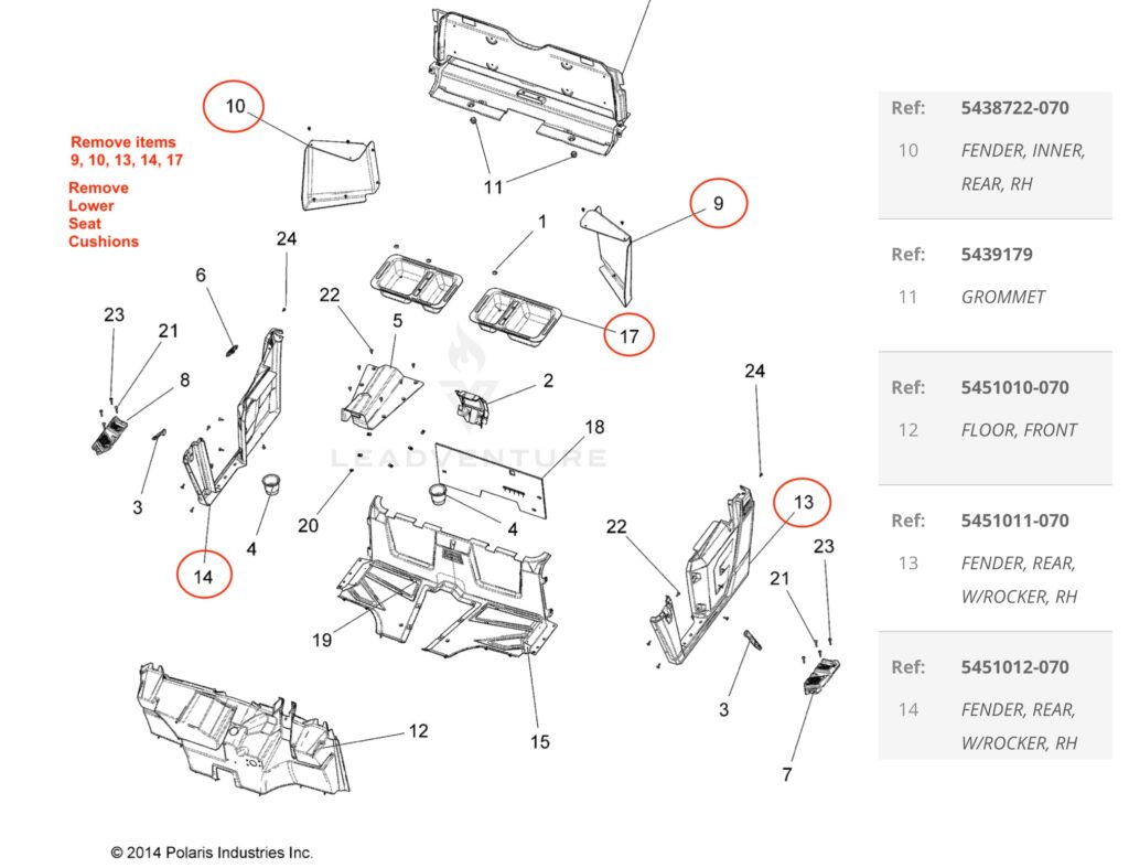
Remove the body panels and inner fender panel on each side of the Ranger to gain access
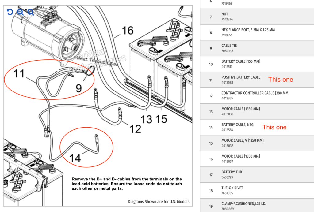
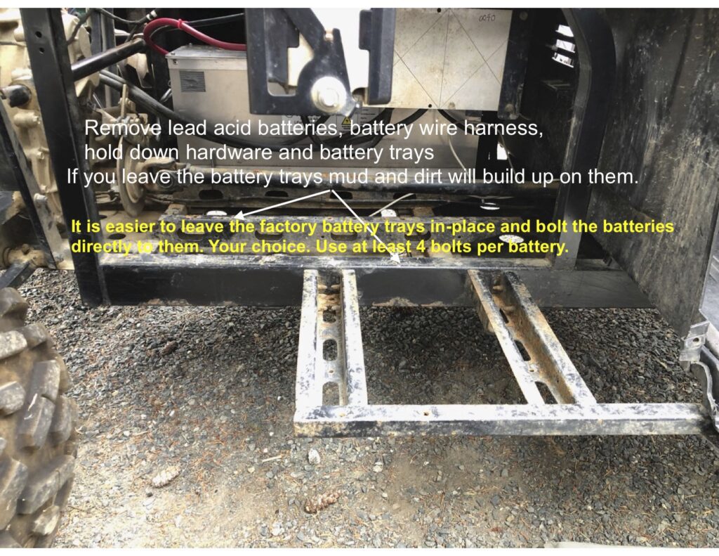
Remove the lead-acid batteries, hold-down hardware, wires and plastic battery tray cover.
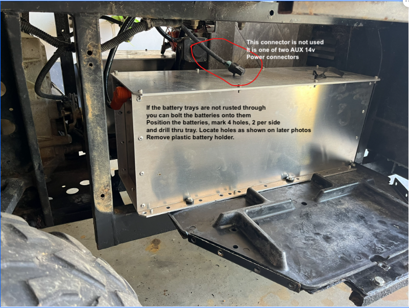
If the battery trays are rusted remove them or clean and repaint them. You can mount the batteries with or without the lead-acid battery trays. You could also install Atlas ESS made Ranger EV Floor Boards and mount the batteries onto them
https://atlas-ess.com/floorboard-installation/
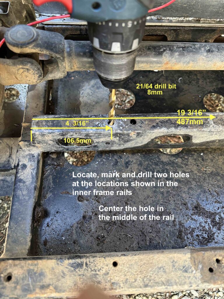
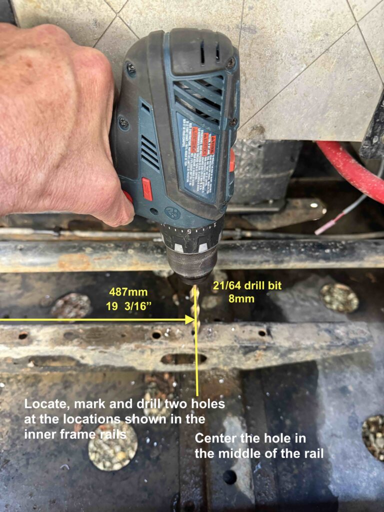
Here we show where to drill holes in the frame rails when the battery trays are removed
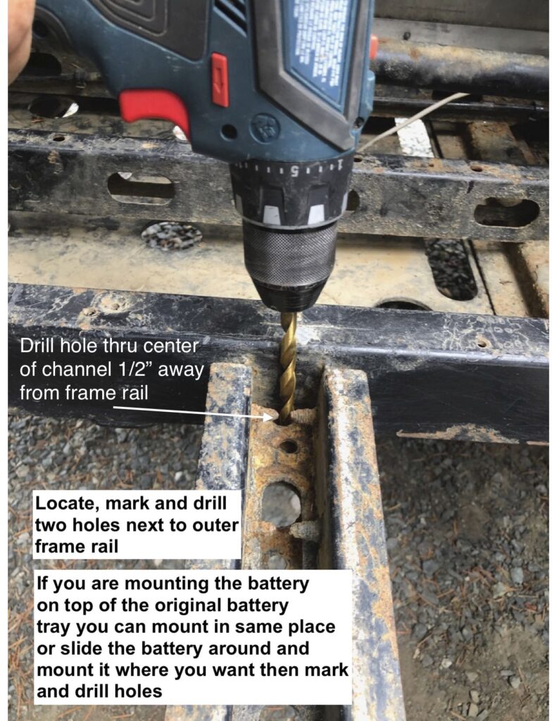
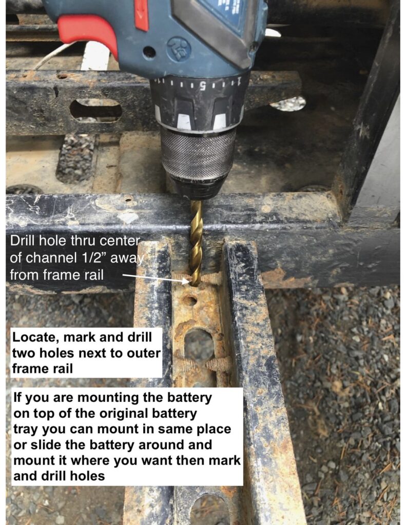
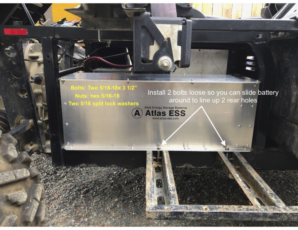
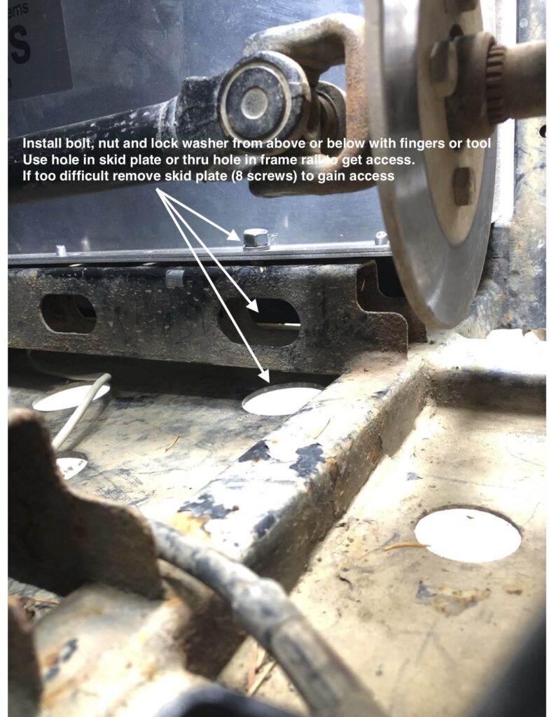
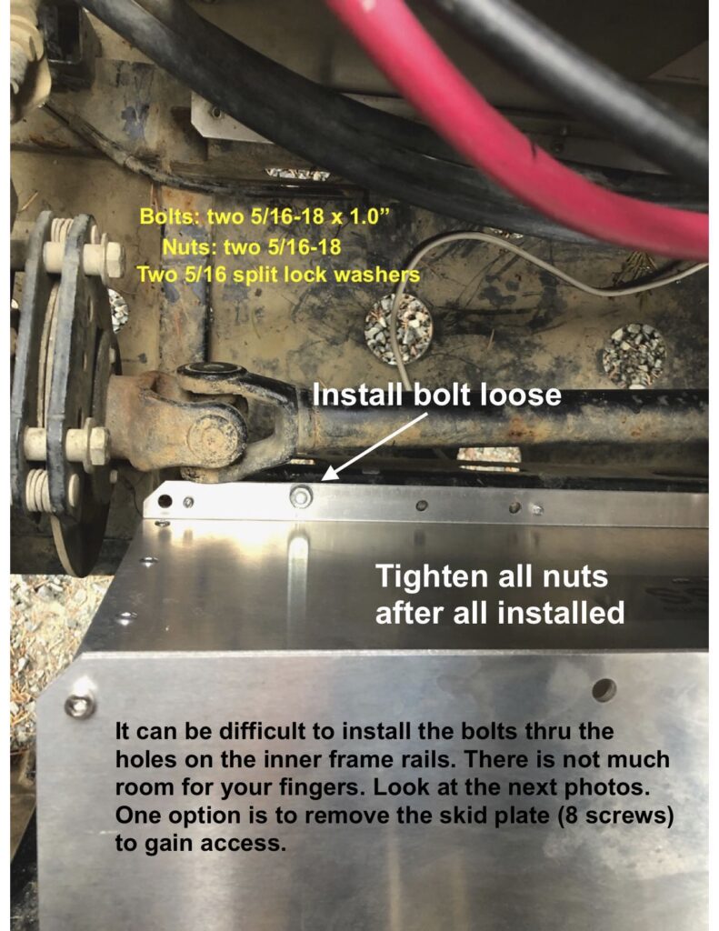
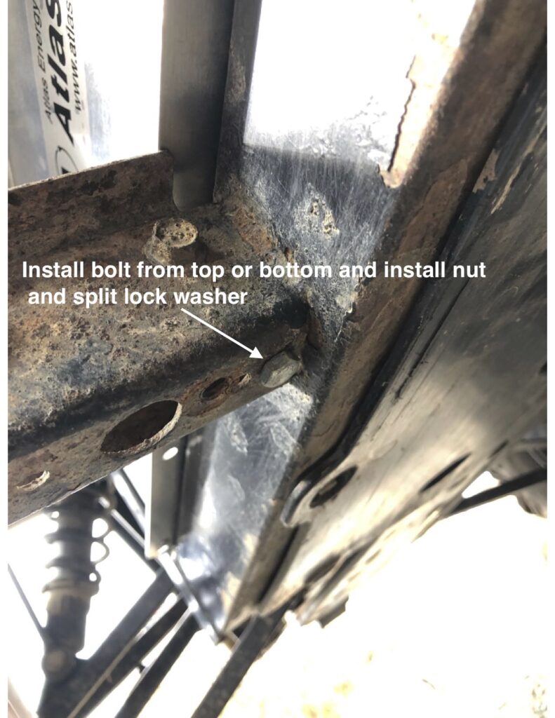
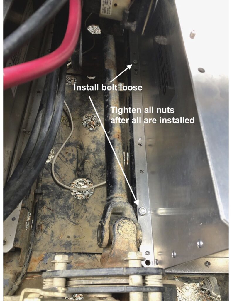
Place the Power Distribution Module PDM on top of a battery. Slide the PDM to the rear of the Ranger to clear the storage tray under the seat.
The PDM is held in place with double sided tape under the PDM
You can change the location of the PDM to suit your needs. Make sure the cables going to the PDM are not under stress (being pulled on)
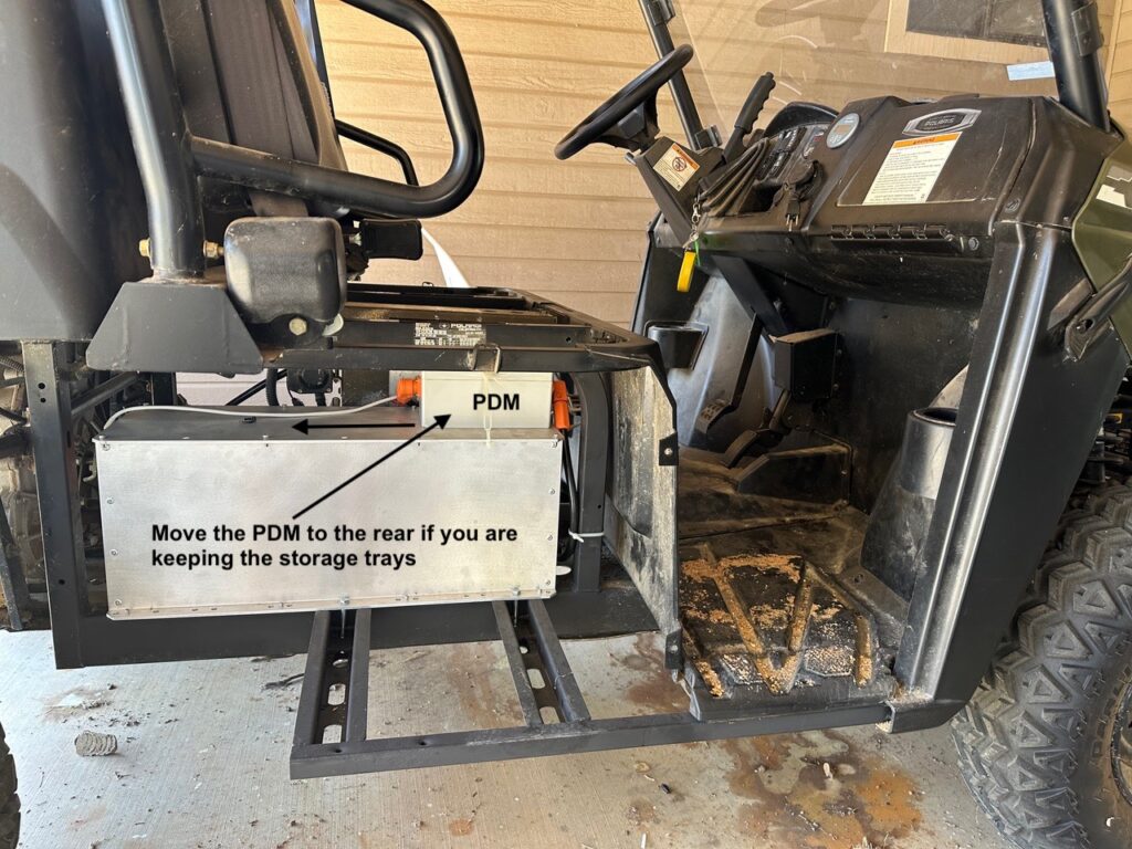
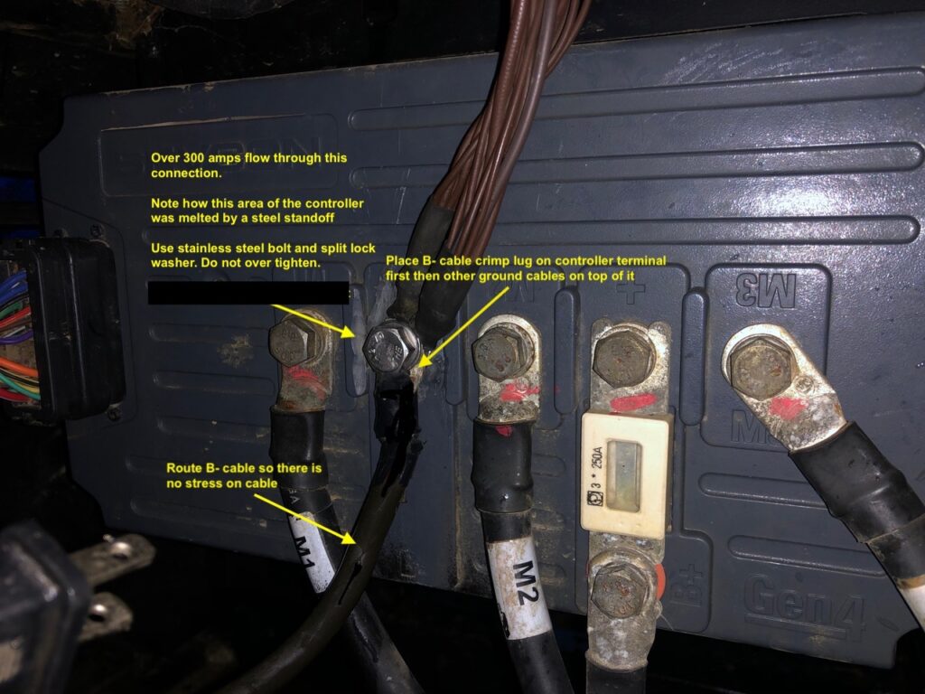
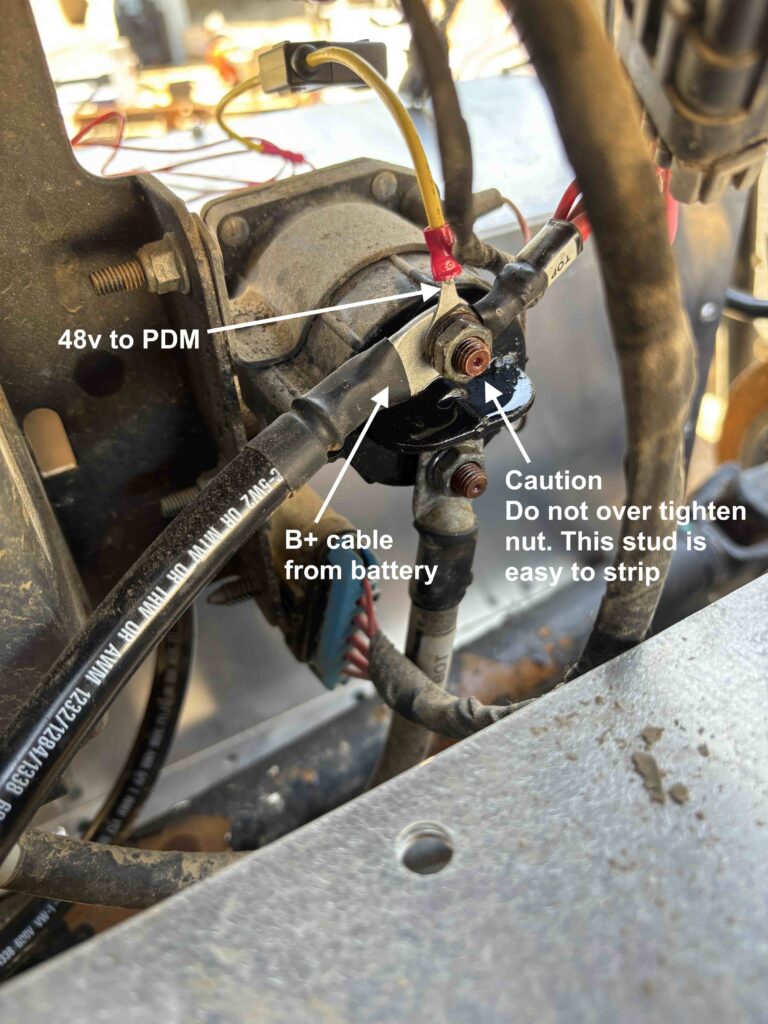
Connect the Power Cables and Cell Loop Cables to the batteries and the PDM
Click the link below for a wiring diagram
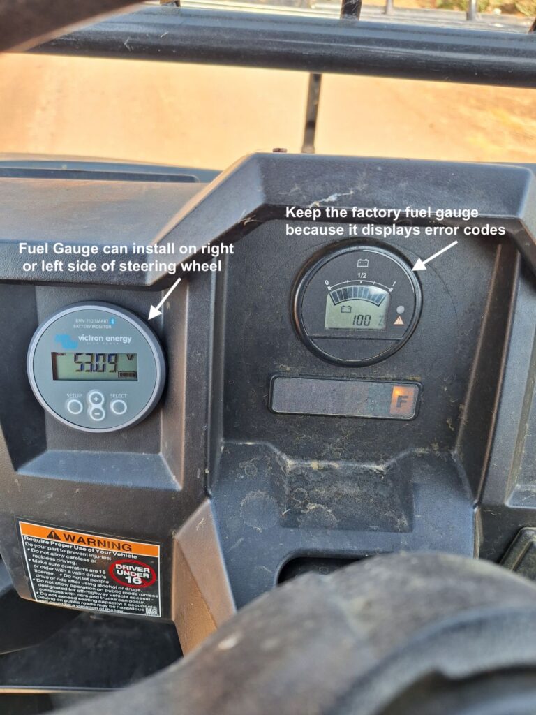
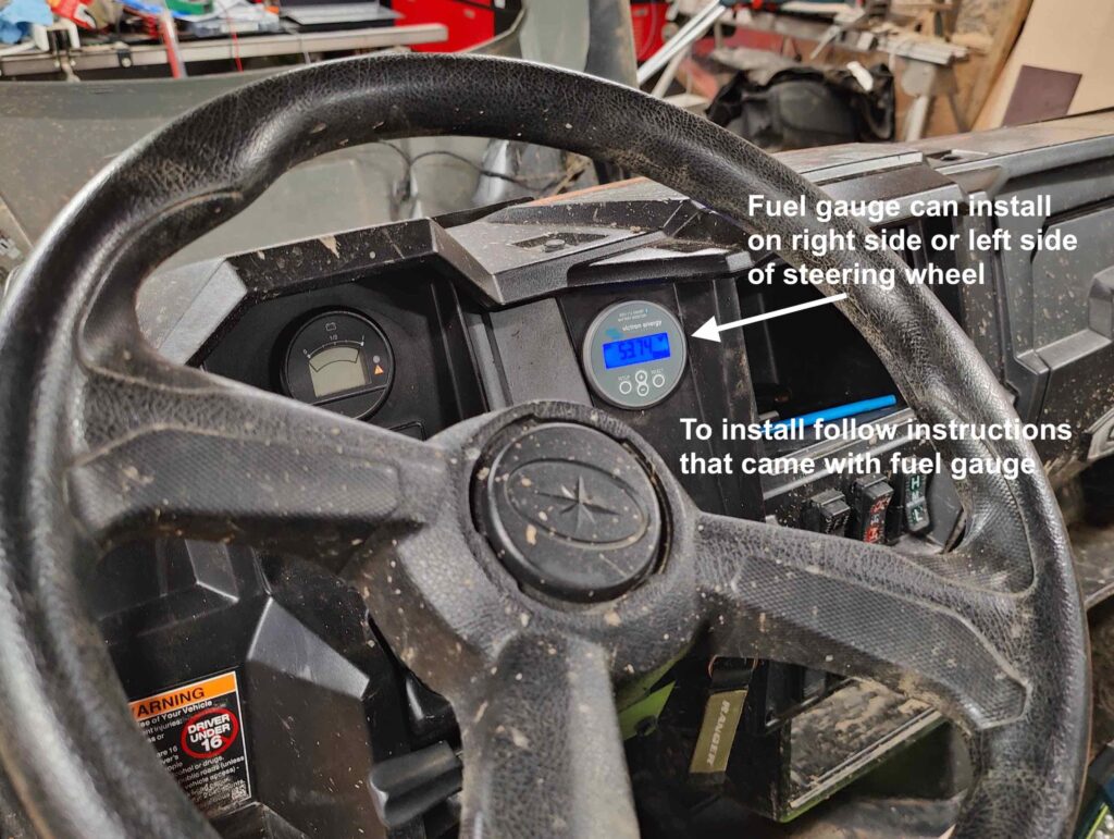
You can replace the factory meter with the Victron gauge and move the factory meter to inside the dash. Keep it connected to its wires
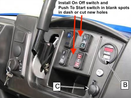
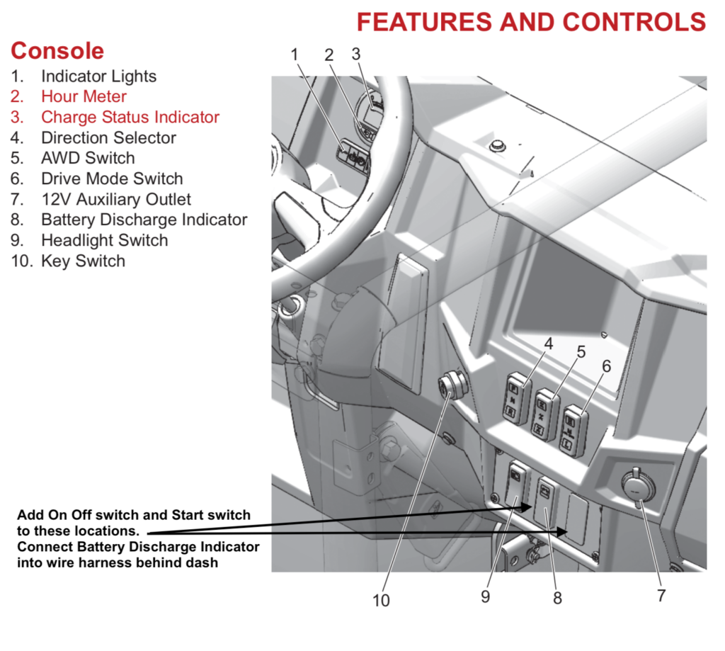
Upgrade Factory Wiring
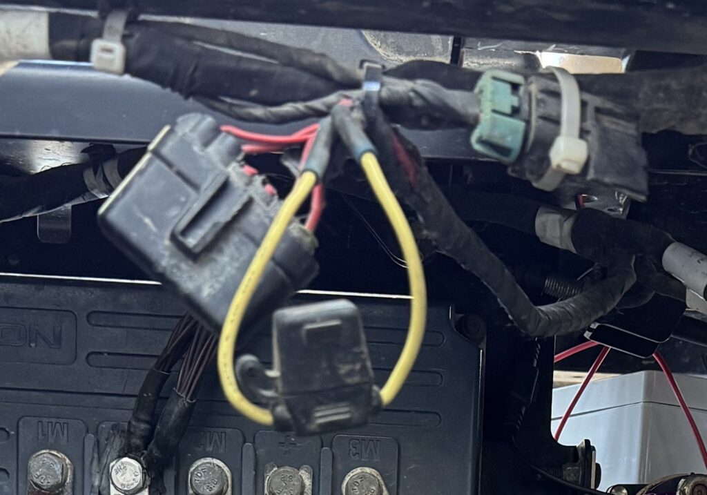
Install ATO Fuse Holder
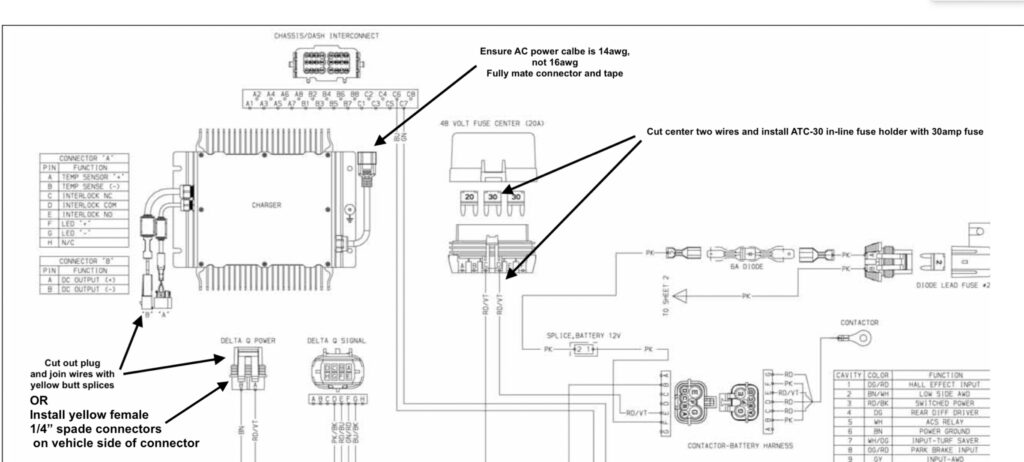
Upgrade the 48v fuse center by installing an ATO fuse holder to replace the center fuse. Cut the wires on the factory fuse holder as shown in the photo and use yellow butt splices to connect the ATO fuse holder. Potential fire hazard in Ranger EV factory wire harness
The center mini blade 30amp fuse in the 48v Fuse Center located under the drivers seat is too light. It can over heat, melt and burn the plastic. Cut off the wires and install a 10awg in- line ATC-30 blade fuse holder and 30amp fuse or similar.
Charger AC Input Cord Must Be 14AWG
The ac cord for the Delta Q charger should be 14awg. The ac plugs can wear out and someone can replace the 14awg with a 16awg computer ac cord. The 16awg cable end that plugs into the charger can get hot enough to melt plastic and burn. The same end can be partially inserted causing the plug to overheat and melt. Wrap electrical tape around the fully seated 14awg plug to keep it together.
Charger DC Output Power Connector Upgrade
The DC Power output cable connector on the battery charger has 2 pins that can be loose and can get hot enough to burn the connector. Cut out the plug on the Ranger side of the connector and install yellow female 1/4" spade connectors onto the 10awg wires. Plug these female spade connectors onto the male pins inside the charger side of the connector.
